metallurgy
ATOMIC
crystal structures
dislocations
diffusion
Metals are crystalline materials, meaning their atoms are arranged in defined crystal structures. One small group of atoms, called a unit cell, has a pattern that repeats throughout the structure. This gives crystalline materials long-range atomic order.
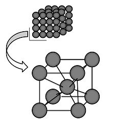
A body-centered cubic unit cell
Many unit cells are based off of a cube with an atom at each corner of the cube. Two of the most common unit cells are called face-centered cubic (FCC) and body-centered cubic (BCC). As the name implies, unit cells that are face-centered cubic have an atom on each of the cube faces, while body-centered cubic has one atom in the center of the cube.
In reality, crystal structures aren't perfect. Atoms can be missing from the lattice, which are called vacancies, or they can be crowded into a new site, called a self-interstitial.
One of the most important imperfections in the crystal structure is called a dislocation. A dislocation is a linear defect that causes a misalignment in the lattice.
As shown above, the atoms outlined in red experience a compressive force; the atoms outlined in green experience a tensile force.
Dislocations can move through a material until they are impeded. Grain boundaries (see below), interstitial atoms, and other dislocations are effective at pinning dislocations. This is the idea behind cold working - plastic deformation creates dislocations, and as the number of dislocations continues to grow, the less mobile they are. This raises the strength of the material, but as plastic deformation becomes limited, brittle failure is more likely.

A dislocation
Interstitial atoms can be added to a metal through solid-solution strengthening. Impurity atoms (an alloy) are added to the crystal structure either as substitutional atoms or interstitial atoms. Steel is a solid-solution strengthened material: carbon, the alloy, is added to iron, the pure metal, and occupies interstitial sites in the iron matrix. The carbon atoms help to impede dislocation movement, making the iron stronger.
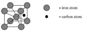
Carbon fills interstitial sites in the iron matrix
Another atomic-scale topic that is of great importance to materials is diffusion. The drive to migrate from high concentration to low concentration is responsible for many phenomena in materials science, and we can manipulate materials through allowing diffusion (heating), and prohibiting diffusion (cooling quickly).
MICROSCOPIC
grains
phase transformations
As the structure of a material forms, atoms align into the crystal structure, and that crystal structure begins to grow. Except this atomic-scale activity is happening throughout the material, not just in one specific spot. Through a process called nucleation, the new crystal structure will form in many locations. This leads to many groups that have the same structure, but different orientations.

Grains
Grain size refinement is one of the most important tools for creating high strength steels. Unlike other strengthening mechanisms, grain size refinement increases both strength and toughness.
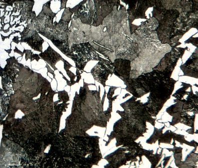
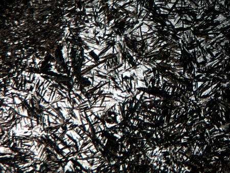
This is what a grain looks like under a microscope
The photo to the left shows grains in a grade of steel. Some of the grains are white, and some of the grains range from medium gray to dark gray. Why do they look different?
One of the reasons steel is so versatile is because it has multiple phases. Steel can exist in multiple microstructures, called phases, which have unique crystal structures and properties. The final phase that exists at room temperature depends on chemistry and cooling.
Above 2500F, steel exists as delta iron, which has a BCC structure. Between 1600-2500F, austenite forms. When slabs exit the continuous caster, or are discharged from the reheat furnace, the have an austenitic structure. Austenite has good hot workability, so it's easy to form a certain shape and/or size in the austenitic phase. Unlike delta iron, austenite is FCC.
Depending on the chemistry and cooling rate, steel under 1600F can exist as a few different phases. Two of the most common phases are ferrite and pearlite. It is important to note that ferrite is BCC - since FCC and BCC have different unit cell arrangements, they also have different volumes. Because of this, there is a volume change as steel cools from austenite to ferrite, which can issues during casting.
At 0.76% carbon, austenite transforms to ferrite, 0.022% carbon, and cementite, 6.70% carbon. Ferrite has a much lower solubility limit for carbon, so the carbon that is rejected from the forming ferrite forms cementite. Ferrite and cementite together form pearlite, which gets its name from its pearlescent appearance under a microscope.

Pearlite under a microscope
Martensite
For steel containing less that 0.76% carbon, the microstructure contains a mixture of ferrite and pearlite. For steel more than 0.76% carbon, the microstructure contains a mixture of pearlite and cementite.
If the steel is cooled rapidly, bainite and martensite can form. Martensite is formed through a diffusionless transformation. When austenite is rapidly quenched, the carbon atoms actually get "stuck" in the interstitial spots they occupy in the FCC lattice. This forms a sort of stretched unit cell cube called body-centered tetragonal, or BCT.
There's an important thermodynamic concept that affects everything in materials science (and outside of materials science, too): things want to minimize their free energy. Ferrite and pearlite form during cooling because they are energetically favorable. Martensite is not energetically favorable, and when given the chance (ie when diffusion is allowed to occur), martensite will transform to a more energetically favorable phase.
Adding alloying elements alters the transformation temperatures in the phase diagram, just as various cooling rates change the final product, but the plain carbon phase diagram is a good source for basic microstructure information.
Continuous cooling curves are used to determine the final microstructure when rapid cooling is in effect.
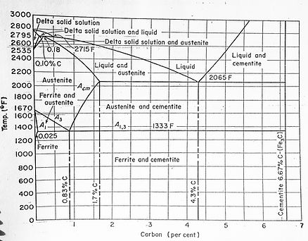
For equilibrium reactions (ie not quenched), the phases present in a plain carbon steel are given by a phase diagram. Carbon percentage is on the horizontal x-axis, and temperature on the vertical y-axis.
The iron-carbon phase diagram
These groups of oriented atoms are called grains. Grains are hugely important in metallurgy; as mentioned above, their ability to impede the motion of dislocations makes them effective at strengthening. The interface between the grains is high-energy, making grain boundaries the preferential site for corrosion, nucleation, and precipitation. Grain boundaries are part of the mechanism of creep, a type of deformation that occurs at elevated temperatures. Grain boundaries also play a role in a material's electrical and thermal conductivity.
MACROSCOPIC
properties
failure
Each room temperature phase has its own unique properties.
-
Ferrite: relatively soft and ductile.
-
Pearlite: harder and stronger than ferrite, but not as ductile.
-
Bainite: harder and stronger than pearlite, but also not as ductile as pearlite.
-
Martensite: very hard and very brittle.
Steels can contain multiple phases at one time; for example, when the carbon percentage is less than 0.76%, grains of both ferrite and pearlite will be present. As the carbon is further reduced, ferrite will be the predominant microstructure, and the properties of the steel will be closer to those of pure ferrite.
Martensite is often present with other microstructures, as it is difficult to form 100% martensite. Due to the rapid cooling needed to form martensite, some austenite is unable to transform and remains at room temperature. This is called retained austenite.
Many advanced grades use a combination of microstructures to achieve desirable properties. Dual phase, an advanced automotive grade, is a mixture of martensite and ferrite. TRIP steels even use the transformation of retained austenite to martensite to reach high strength levels without forfeiting formability.
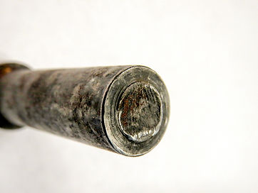
Bolt failure
Failures in a steel parts are commonly due to overload, fatigue, environmental factors, or a combination of the three.
Overload failure happens when the stress in a part is greater than its load-bearing capacity (tensile stress). This could happen because a critical crack propagated through the material, or because the part was under-designed, or because it was weakened by embrittlement.
-
Ductile fracture occurs when the material is able to absorb energy through plastic deformation. There are physical signs of failure - bending, stretching, etc.
-
Brittle fracture occurs suddenly with little warning. Unlike ductile fracture, there is little to no permanent deformation, so almost no energy is absorbed. This can be catastrophic. The Charpy V-notch test is a helpful tool in determining whether a material's fracture will be brittle or ductile.
Fatigue is a cyclic failure; these failures can occur over a long period of time, and at stress levels below the tensile stress of the material. Cracks initiate at stress concentrations (grain boundaries, inclusions, part geometry, etc.) and grow as the cyclic loading continues. Once the crack reaches a critical size, the material will fracture. Cyclic loading affects car axles, airplane wings, paper clips - any parts that are repeatedly loaded and unloaded or experience alternating stresses.
Environmental factors are often a supporting factor in a failure. The environment can weaken a material, which then becomes susceptible to overload or fatigue. For example, many aluminum, titanium, and steel alloys have shown to be adversely affected by water during fatigue testing. Hydrogen embrittlement, which can occur through processing, limits strength.
One of the most difficult environmental factors to control is corrosion. Some metals develop protective oxide layers on the surface that prevent corrosion, such as aluminum. Stainless steels have a high chromium content, and the chromium oxide that forms on the surface protects the stainless steel from rusting. Plain carbon and alloy steel do not form a protective layer - iron oxides, or rust, do not inhibit the corrosion reaction taking place on the surface of the steel, and the steel will continue to rust. If the rusting is allowed to continue, it can affect the structural integrity of the steel; think of the vehicles that are so corroded around the wheel wells and tailgates that chunks of steel appear to be missing.
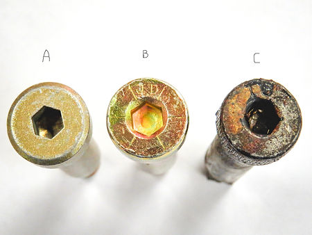

A rusted shoulder bolt (C) fractured in service
Existing defects are oftentimes the origin of failure. These defects can be the initiation site for cracks, which propagate through a material when it is loaded, weakening it.
These defects can be created from the part design, during casting and rolling, processing and manufacturing, and in-service.
-
Part design: improper material selection, stress concentrations, inappropriate surface treatments
-
Casting and rolling: inclusions, second phase particles, seams, delaminations, decarburization
-
Processing and manufacturing: scratches, gouges, machining and stamping marks, welding defects such as porosity and cracking
-
In-service: corrosion damage, hydrogen embrittlement, stress corrosion cracking
